How to connect ESP8266
In this tutorial, we will look at how to connect an ESP8266 board to the Kaa platform using the default MQTT-based protocol. You will learn how to create a digital twin of your device, connect it, submit some telemetry, and view it in the Kaa web interface.
Overview
We will simulate a weather station scenario. Our ESP8266 will represent an endpoint in the Kaa platform and report temperature, humidity, and the CO2 level. Also, we will interact with the Kaa Web Dashboard to create a digital twin of the ESP8266 and view telemetry data.
Note that for simplicity the reported values are simulated, however, you are welcome to extend the functionality by connecting sensors to your board and reporting real data.
Prerequisites
- You have installed the Arduino IDE.
- You have an ESP8266 board.
- You have a Kaa Cloud account.
Playbook
Connect your device
1. Go to the “Device management” dashboard in your Kaa Cloud account.
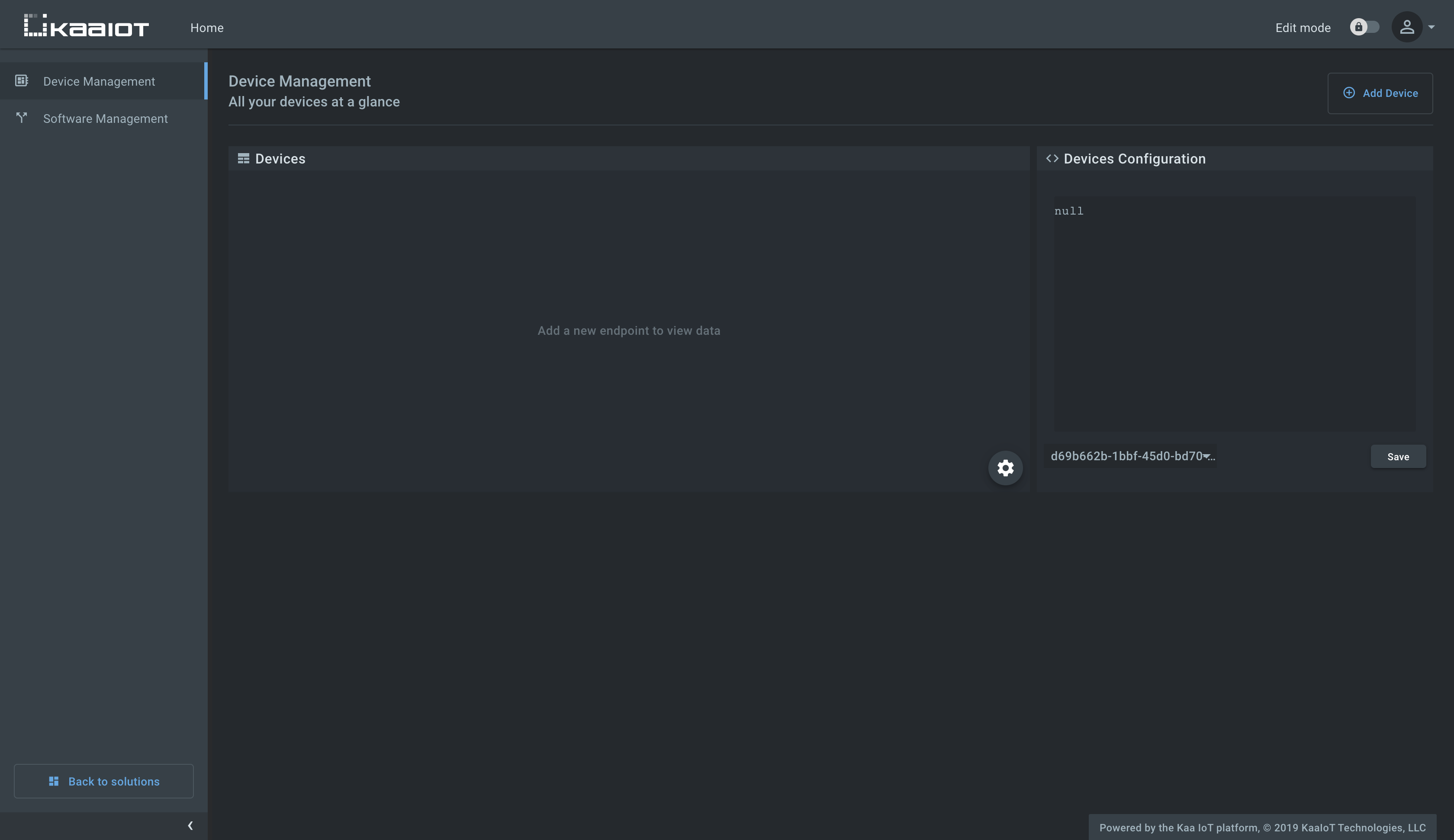
As you can see, there are no connected devices yet. Let’s connect one.
2. Click “Add device” to start registering a device digital twin. It’s called an “endpoint” in Kaa.
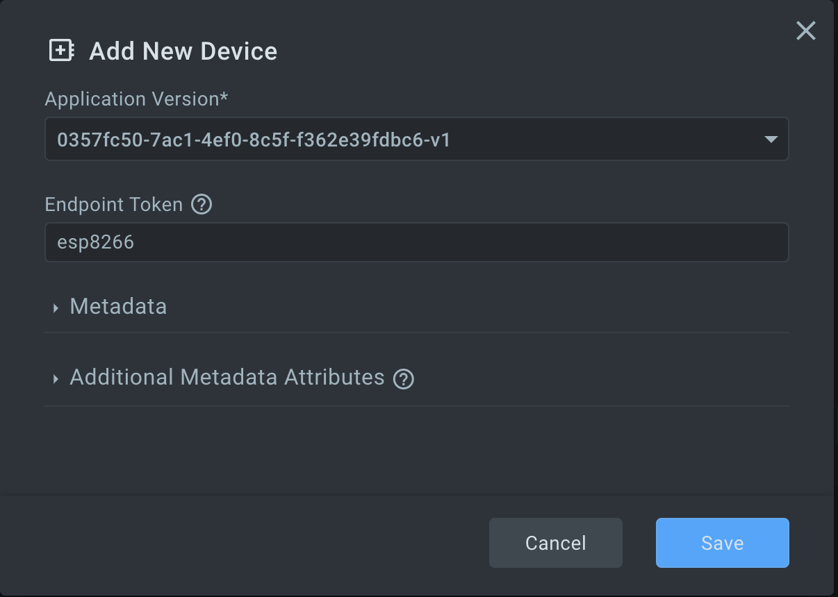
3. Choose the application version from the drop-down menu. You can increment application versions in the application administration page as your devices evolve. Enter the desired endpoint token.
Tokens are used for device identification in communication with the Kaa platform.
They are non-empty strings that do not contain the following reserved characters: +, #, /, and ..
A token will be autogenerated if you leave this field blank.
Enter endpoint metadata and click Save button.
Metadata is simply key-value attributes that provide certain information about a device, e.g. its location, owner, customer, model, etc.
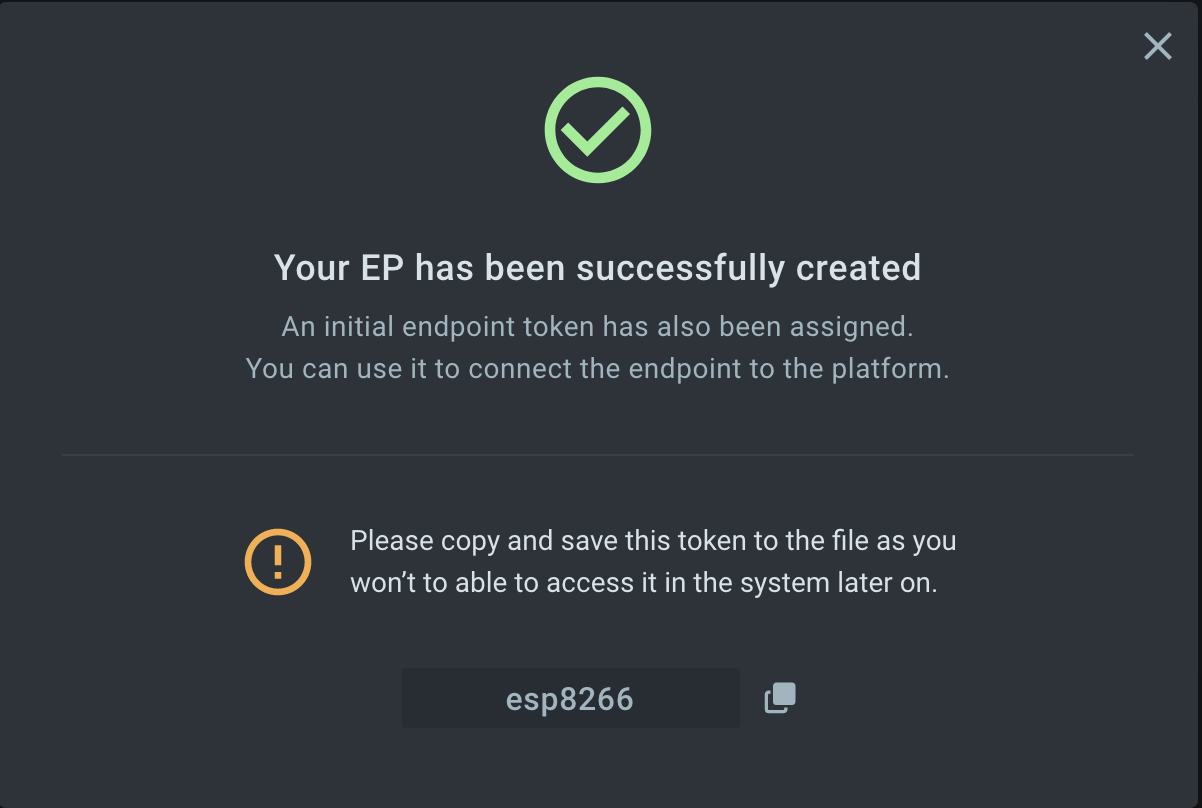
4. Copy and save the endpoint token in some file because you won’t be able to see it again in the future. We will use the token in a bit to connect the simulator.
5. Open the esp8266.ino file with the Arduino IDE and fill out the connection parameters:
const char* ssid = "";          // your WiFi network SSID
const char* password = "";      // your WiFi network password
const String TOKEN = "";        // the endpoint token from the previous step
const String APP_VERSION = "";  // the application version name you are working with
6. Upload the esp8266.ino file to your ESP8266.
Now the device can send telemetry data with the temperature, humidity, and CO2 values. The data payload is a UTF-8 encoded JSON array as seen below.
[
  {
    "temperature":23,
    "humidity":57,
    "co2":720
  }
]
See Data Collection Protocol RFC for more details on the payload format.
Visualize data from the device
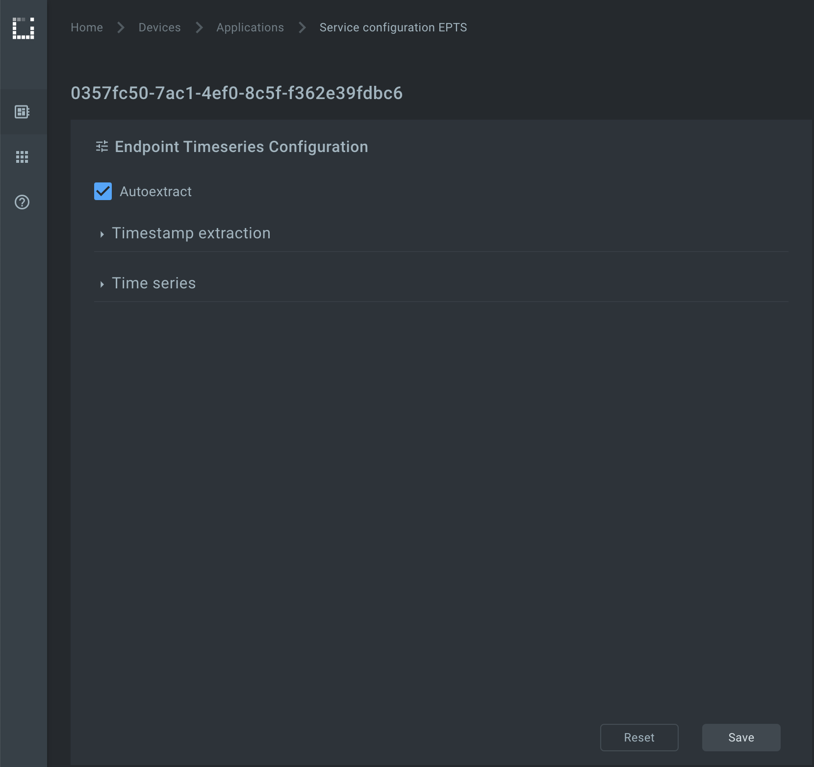
1. Edit the application configuration for the Endpoint Time Series service (EPTS). EPTS is a Kaa platform component that is responsible for transforming raw data samples into well-structured time series. It also stores the timeseries data and provides access API for other services, including the Web Dashboard.
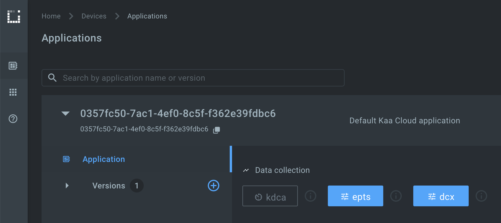
Enable the time series auto-extraction from data samples.
2. Go to the device details page of the recently created endpoint (by clicking on the corresponding row in the device table).
See the data from your ESP on the DEVICE TELEMETRY widget.
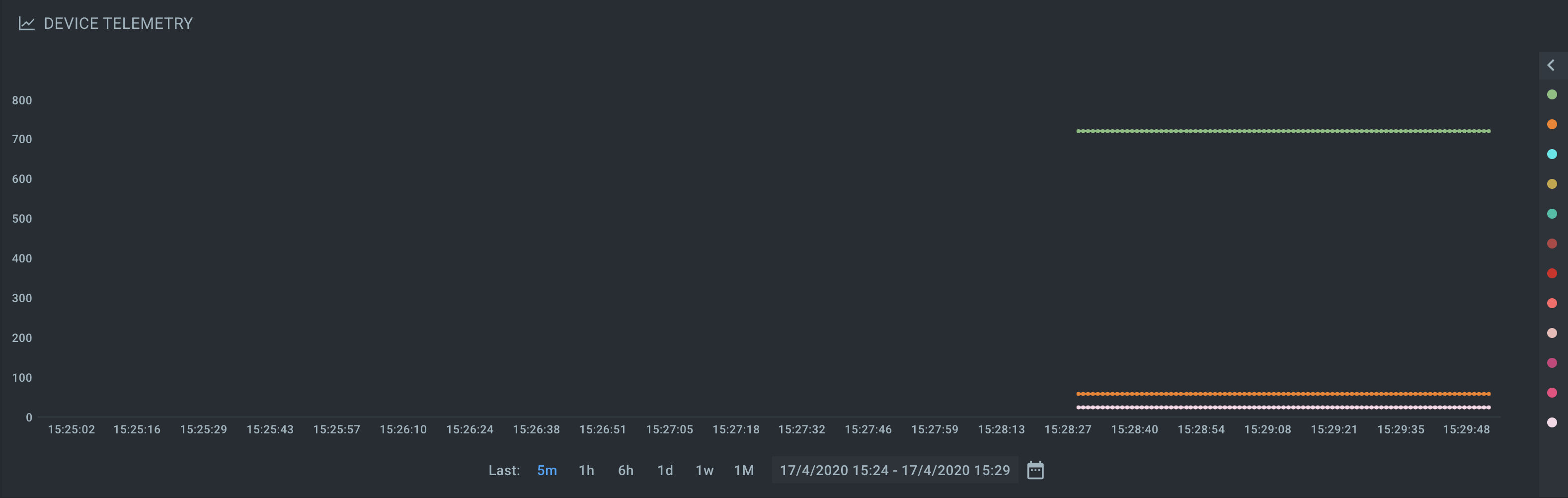
Congratulations, you have connected and visualized data from your ESP8266!
Resources
- All tutorial resources are located on GitHub.
Next steps
- Complete the Getting Started tutorials cycle with short tutorials about the main Kaa features.
- Join the discussion at our community chat and share feedback!
- Outfit your ESP8266 with sensors to collect real data.
- Now that you have some Kaa experience under your belt, check out the Kaa IoT Cloud and Kaa 1.1 webinar to implement something more advanced.
- Data Analytics and Notifications webinar is also based on an ESP8266-powered smart socket.
- Device management - find out more about the device management feature.