How to connect STM32
In this tutorial, we will look at how to connect an STM32 board to the Kaa platform using Kaa IoT Platform Arduino library. You will learn how to create a digital twin of your device, connect it, send telemetry and receive commands.
Overview
Our STM32 board will represent an endpoint in the Kaa platform, report its built-in LED state and allow to control it from the Kaa UI.
Prerequisites
- You have installed the Arduino IDE.
- You have a STM32 Nucleo board and Ai-Thinker ESP8266 ESP-01 module with Ai-Thinker AT firmware.
- You have a Kaa Cloud account.
Playbook
Connect your device
1. Go to the “Device management” dashboard in your Kaa Cloud account.
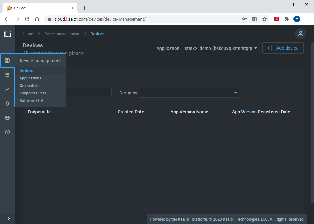
2. Choose the application version from the drop-down menu and register a device digital twin by clicking “Add Device” button. It’s called an “endpoint” in Kaa.
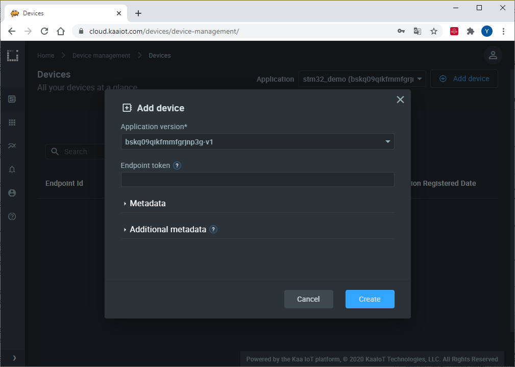
3. Enter the desired endpoint token and click “Create”.
Tokens are used for device identification in communication with the Kaa platform.
They are non-empty strings that do not contain the following reserved characters: +, #, /, and ..
A token will be autogenerated if you leave this field blank.
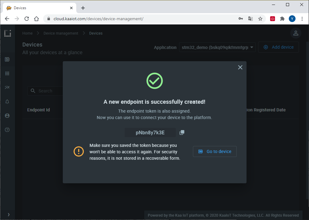
4. Copy and save the endpoint token in some file because you won’t be able to see it again in the future. We will use the token in a bit to connect the simulator.
5. Open the below sketch in the Arduino IDE and fill out the connection parameters:
#define KAA_TOKEN ""        // Endpoint token
#define KAA_APP_VERSION ""  // Application version that endpoint works in

#define WIFI_SSID ""       // Your WiFi network SSID
#define WIFI_PASS ""       // Your WiFi network password

#define KAA_HOST "mqtt.cloud.kaaiot.com"
#define KAA_PORT 1883

#define RECONNECT_TIME  5000 //ms
#define SEND_TIME       3000 //ms

#define COMMAND_TYPE "OUTPUT_SWITCH"
#define OUTPUT_1_NAME "output_1"

// Select your modem:
//#define TINY_GSM_MODEM_SIM800
// #define TINY_GSM_MODEM_SIM808
// #define TINY_GSM_MODEM_SIM868
// #define TINY_GSM_MODEM_SIM900
// #define TINY_GSM_MODEM_SIM7000
// #define TINY_GSM_MODEM_SIM5360
// #define TINY_GSM_MODEM_SIM7600
// #define TINY_GSM_MODEM_UBLOX
// #define TINY_GSM_MODEM_SARAR4
// #define TINY_GSM_MODEM_M95
// #define TINY_GSM_MODEM_BG96
// #define TINY_GSM_MODEM_A6
// #define TINY_GSM_MODEM_A7
// #define TINY_GSM_MODEM_M590
// #define TINY_GSM_MODEM_MC60
// #define TINY_GSM_MODEM_MC60E
 #define TINY_GSM_MODEM_ESP8266
// #define TINY_GSM_MODEM_XBEE
// #define TINY_GSM_MODEM_SEQUANS_MONARCH

// Increase RX buffer if needed
#define TINY_GSM_RX_BUFFER 1024

// Set serial for debug console (to the Serial Monitor, default speed 115200)
#define SerialMon Serial

// Set serial for AT commands (to the module)
// Use Hardware Serial on Mega, Leonardo, Micro, STM32
HardwareSerial Serial3(PC11, PC10);
#define SerialAT Serial3

// or Software Serial on Uno, Nano
//#include <SoftwareSerial.h>
//SoftwareSerial SerialAT(2, 3); // RX, TX

// See all AT commands, if wanted
// #define DUMP_AT_COMMANDS

// Define the serial console for debug prints, if needed
#define TINY_GSM_DEBUG SerialMon

// Range to attempt to autobaud
#define GSM_AUTOBAUD_MIN 9600
#define GSM_AUTOBAUD_MAX 115200

// Add a reception delay - may be needed for a fast processor at a slow baud rate
// #define TINY_GSM_YIELD() { delay(2); }

// Define how you're planning to connect to the internet
#define TINY_GSM_USE_GPRS false
#define TINY_GSM_USE_WIFI true

// set GSM PIN, if any
#define GSM_PIN ""

// Your GPRS credentials, if any
const char apn[] = "YourAPN";
const char gprsUser[] = "";
const char gprsPass[] = "";

// Your WiFi connection credentials, if applicable
const char wifiSSID[] = WIFI_SSID;
const char wifiPass[] = WIFI_PASS;

// MQTT details
const char* broker = KAA_HOST;

#include <TinyGsmClient.h>
#include <PubSubClient.h>
#include <ArduinoJson.h>
#include <kaa.h>

// Just in case someone defined the wrong thing..
#if TINY_GSM_USE_GPRS && not defined TINY_GSM_MODEM_HAS_GPRS
#undef TINY_GSM_USE_GPRS
#undef TINY_GSM_USE_WIFI
#define TINY_GSM_USE_GPRS false
#define TINY_GSM_USE_WIFI true
#endif
#if TINY_GSM_USE_WIFI && not defined TINY_GSM_MODEM_HAS_WIFI
#undef TINY_GSM_USE_GPRS
#undef TINY_GSM_USE_WIFI
#define TINY_GSM_USE_GPRS true
#define TINY_GSM_USE_WIFI false
#endif

#ifdef DUMP_AT_COMMANDS
  #include <StreamDebugger.h>
  StreamDebugger debugger(SerialAT, SerialMon);
  TinyGsm modem(debugger);
#else
TinyGsm modem(SerialAT);
#endif
TinyGsmClient client(modem);
PubSubClient mqtt(client);
Kaa kaa(&mqtt, KAA_TOKEN, KAA_APP_VERSION);

#define LED_PIN LED_BUILTIN
int ledStatus = LOW;

uint32_t last_reconnect = 0;
uint32_t last_msg = 0;

void mqttCallback(char* topic, byte* payload, unsigned int len) {
  SerialMon.print("Message arrived [");
  SerialMon.print(topic);
  SerialMon.print("]: ");
  SerialMon.write(payload, len);
  SerialMon.println();

  kaa.messageArrivedCallback(topic, (char*)payload, len);
}

boolean mqttConnect() {
  SerialMon.print("Connecting to ");
  SerialMon.print(broker);

  // Connect to MQTT Broker
  boolean status = mqtt.connect("STM32Client");

  // Or, if you want to authenticate MQTT:
  //boolean status = mqtt.connect("GsmClientName", "mqtt_user", "mqtt_pass");

  if (status == false) {
    SerialMon.println(" fail");
    return false;
  }
  SerialMon.println(" success");

  kaa.connect();
  composeAndSendMetadata();

  return mqtt.connected();
}


void setup() {
  // Set console baud rate
  SerialMon.begin(115200);
  delay(10);

  pinMode(LED_PIN, OUTPUT);

  // !!!!!!!!!!!
  // Set your reset, enable, power pins here, if needed
  // !!!!!!!!!!!

  kaa.setCommandCallback(&commandCallback);

  SerialMon.println("Wait...");

  // Set GSM module baud rate
  //TinyGsmAutoBaud(SerialAT, GSM_AUTOBAUD_MIN, GSM_AUTOBAUD_MAX);
  SerialAT.begin(115200);
  //delay(6000);

  // Restart takes quite some time
  // To skip it, call init() instead of restart()
  SerialMon.println("Initializing modem...");
  modem.restart();
  //modem.init();

  String modemInfo = modem.getModemInfo();
  SerialMon.print("Modem Info: ");
  SerialMon.println(modemInfo);

#if TINY_GSM_USE_GPRS
  // Unlock your SIM card with a PIN if needed
  if ( GSM_PIN && modem.getSimStatus() != 3 ) {
    modem.simUnlock(GSM_PIN);
  }
#endif

#if TINY_GSM_USE_WIFI
    // Wifi connection parameters must be set before waiting for the network
  SerialMon.print(F("Setting SSID/password..."));
  if (!modem.networkConnect(wifiSSID, wifiPass)) {
    SerialMon.println(" fail");
    delay(10000);
    return;
  }
  SerialMon.println(" success");
#endif

#if TINY_GSM_USE_GPRS && defined TINY_GSM_MODEM_XBEE
  // The XBee must run the gprsConnect function BEFORE waiting for network!
  modem.gprsConnect(apn, gprsUser, gprsPass);
#endif

  SerialMon.print("Waiting for network...");
  if (!modem.waitForNetwork()) {
    SerialMon.println(" fail");
    delay(10000);
    return;
  }
  SerialMon.println(" success");

  if (modem.isNetworkConnected()) {
    SerialMon.println("Network connected");
  }

#if TINY_GSM_USE_GPRS
  // GPRS connection parameters are usually set after network registration
    SerialMon.print(F("Connecting to "));
    SerialMon.print(apn);
    if (!modem.gprsConnect(apn, gprsUser, gprsPass)) {
      SerialMon.println(" fail");
      delay(10000);
      return;
    }
    SerialMon.println(" success");

  if (modem.isGprsConnected()) {
    SerialMon.println("GPRS connected");
  }
#endif

  // MQTT Broker setup
  mqtt.setServer(broker, KAA_PORT);
  mqtt.setCallback(mqttCallback);
}

void loop() {

  if (!mqtt.connected()) {
    SerialMon.println("=== MQTT NOT CONNECTED ===");
    // Reconnect every 10 seconds
    uint32_t t = millis();
    if (t - last_reconnect > 10000L) {
      last_reconnect = t;
      if (mqttConnect()) {
        last_reconnect = 0;
      }
    }
    delay(100);
    return;
  }

  mqtt.loop();

  uint32_t now = millis();
  if ( ((now - last_msg) > SEND_TIME) || (now < last_msg) )
  {
    last_msg = now;
    //Send something here
    sendOutputsState();
  }
}

void composeAndSendMetadata() {
  StaticJsonDocument<255> doc_data;

  doc_data["name"] = "STM32";
  doc_data["model"] = "Nucleo";
  doc_data["location"] = "Kyiv";
  doc_data["longitude"] = 50.465647;
  doc_data["latitude"] = 30.515270;

  kaa.sendMetadata(doc_data.as<String>().c_str());
}

void changeOutputState(int output_number, int output_state) {
  digitalWrite(LED_BUILTIN, output_state);
  sendOutputsState();
}

void sendOutputsState() {
  StaticJsonDocument<255> doc_data;

  doc_data.createNestedObject();
  doc_data[0][OUTPUT_1_NAME] = digitalRead(LED_BUILTIN);

  kaa.sendDataRaw(doc_data.as<String>().c_str());
}

int commandCallback(char* command_type, char* payload, unsigned int len) {
  if (!strcmp(command_type, COMMAND_TYPE)) {
    DynamicJsonDocument doc(1023);
    //StaticJsonDocument<255> doc;
    deserializeJson(doc, payload, len);
    JsonVariant json_var = doc.as<JsonVariant>();

    SerialMon.printf("Used command_id = %d\n", json_var[0]["id"].as<unsigned int>());
    int output_number = json_var[0]["payload"]["number"].as<int>();
    int output_state = json_var[0]["payload"]["state"].as<int>();
    changeOutputState(output_number, output_state);

    kaa.sendCommandResultAllIds(command_type, json_var);
  } else {
    SerialMon.print("Unknown command\n");
  }
  return 0;
}
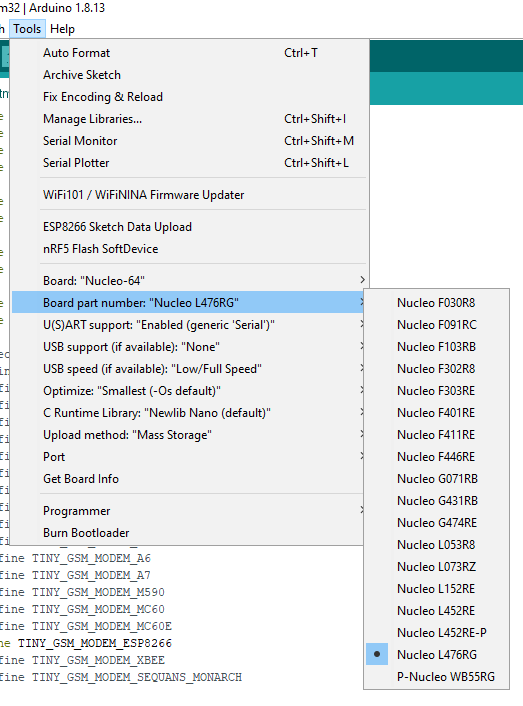
6. Install STM32duino Arduino_Core_STM32. You may do it via Arduino Boards manager (search for “STM32 Cores”)
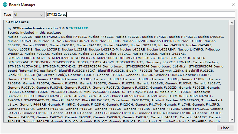
After the installation, choose the correct board. In this example, we will use Nucleo L476RG, but it should work with other boards, too.
Also install Kaa IoT Platform Arduino library, TinyGSM and ArduinoJSON libraries using Arduino library manager.
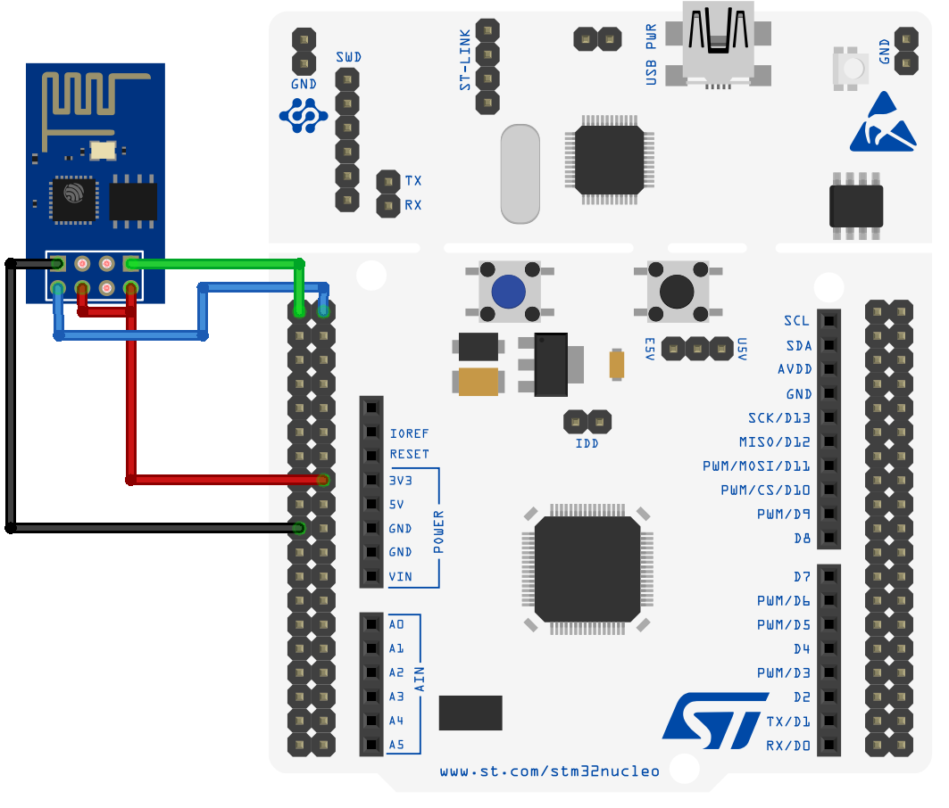
7. Connect ESP8266 to STM32 as shown in the below diagram.
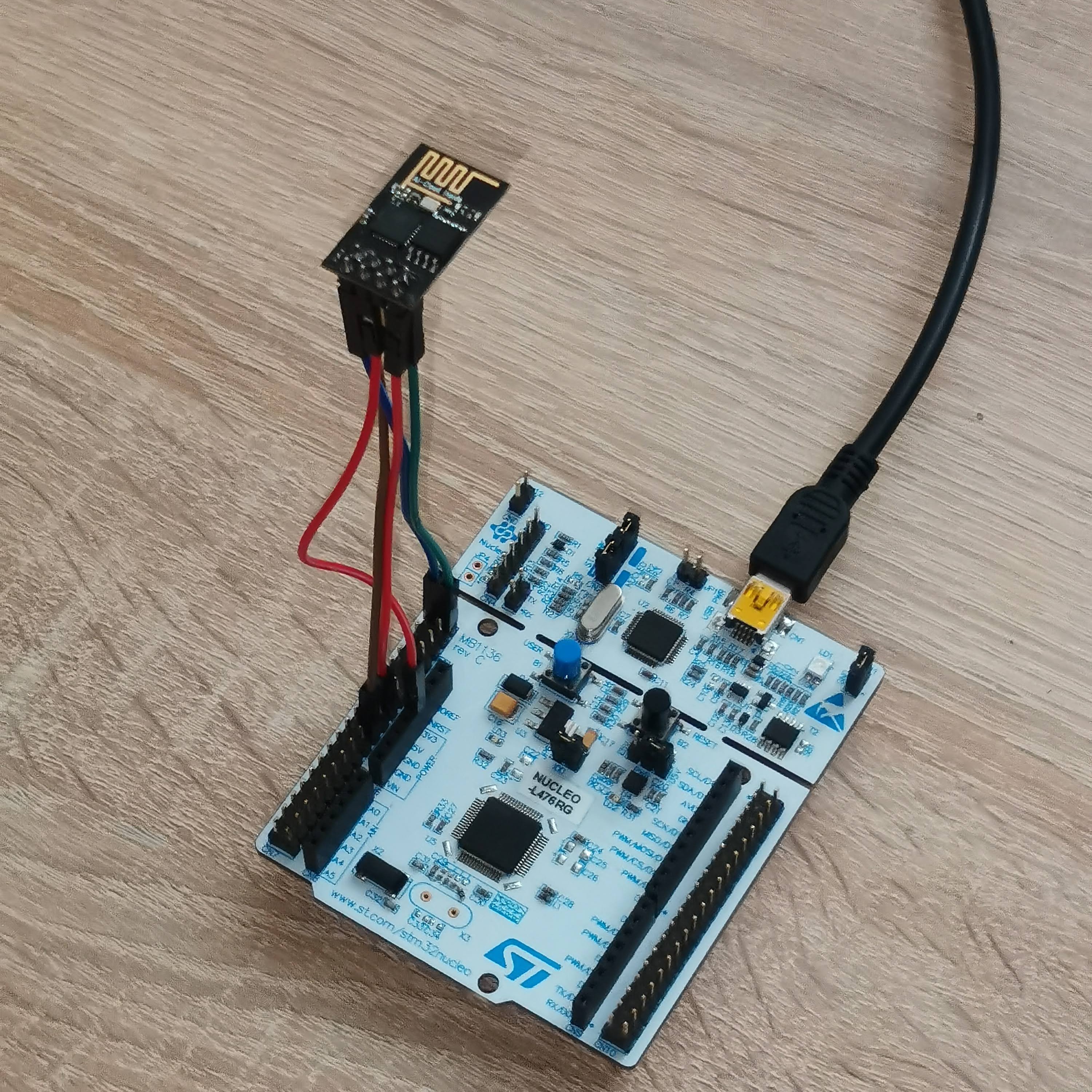
The resulting set-up must look like this.
8. Upload the sketch file to your STM32.
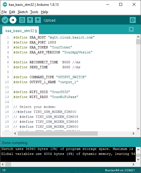
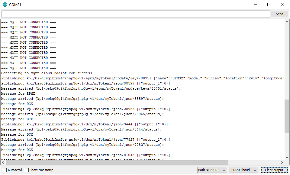
After the upload, open a serial monitor. If everything is ok, you will see the following output:
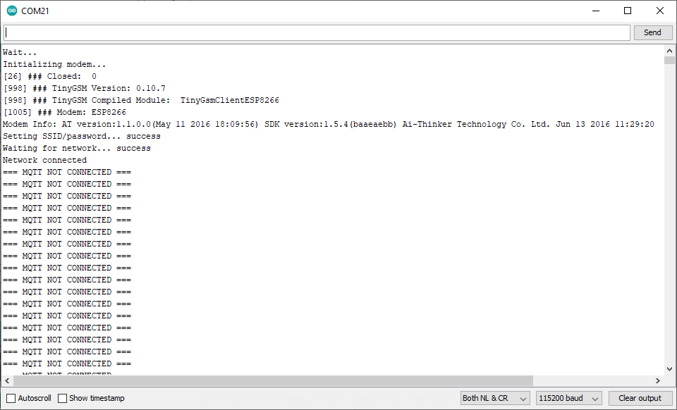
In a few seconds, the device connects to the Kaa Cloud and starts sending data.
Visualize data from the device
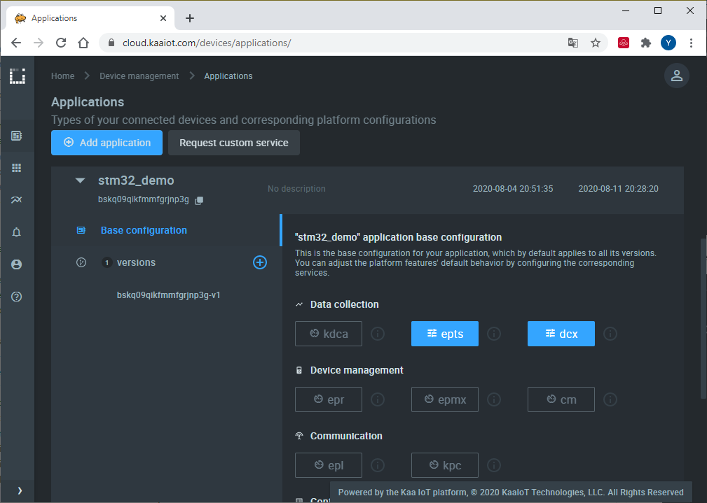
1. Now we want to transform raw telemetry into time series to be able to visualize it. For that navigate to the “Device management” -> “Applications” and edit the application configuration for the Endpoint Time Series service (EPTS). EPTS is a Kaa platform component that is responsible for transforming raw data samples from endpoints into well-structured time series. It also stores the time series data and provides access API for other services, including the Web Dashboard.
Enable the time series auto-extraction from data samples.
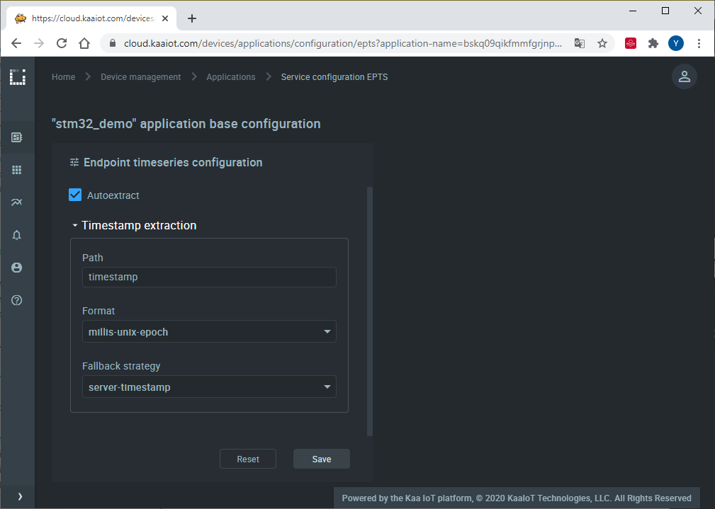
With this function enabled, Kaa will automatically create a time series for each numeric field it encounters at the root of data samples submitted by your endpoints. You will then be able to view these time series in Kaa UI, no extra configuration is required.
2. Go to the “Device management” page and open device details of the recently created endpoint (by clicking on the corresponding row in the device table).
Here you can see all the device telemetry and metadata.
Our board is sending one value output_1 that represents a state of an onboard LED.
The platform prefixed its time series name with the auto~, meaning it was auto-extracted.
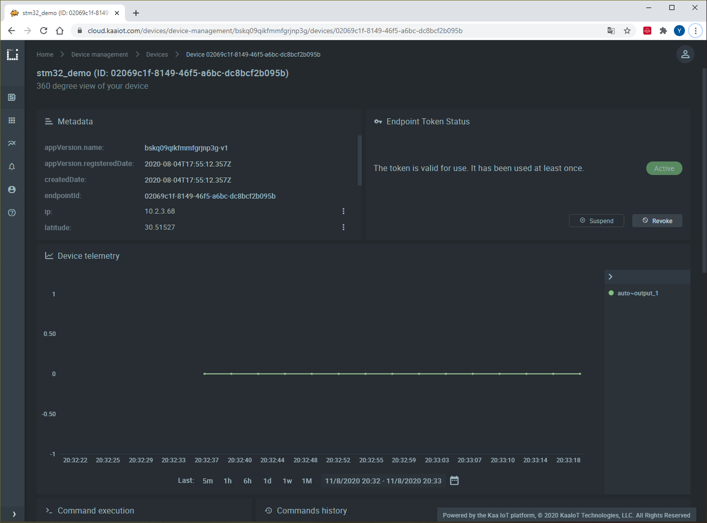
You can control the LED directly from this page.
Scroll down and find the Command execution widget.
Fill out the Command type field with OUTPUT_SWITCH and Command body in JSON field with { "number": "1", "state": "1" } to turn on the LED.
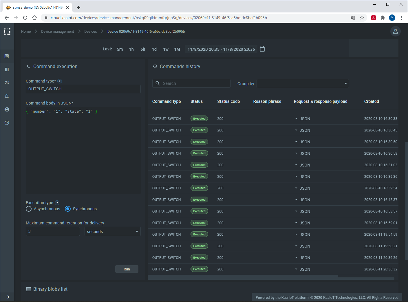
"number" is an output number and "state" is the LED state.
We have one output pin with the LED connected to it, so we named it the first output or output number 1 in the device firmware.
If we have more outputs, we may refer to them in a similar way.
To turn off the LED, change "state" to zero: { "number": "1", "state": "0" }.
Further, you may configure your dashboard with a command execution widget to do all of the above in one click.
Resources
- All tutorial resources are located on GitHub.
Next steps
- Complete the Getting Started tutorials cycle with short tutorials about the main Kaa features.
- Join the discussion at our community chat and share feedback!
- Outfit your STM32 with sensors to collect more data.